

PiBoy a.k.a. GameBoy on Steroids
- May 28, 2016
- 6 min read
It started when I stumbled across this particular posting on adafruit.com. On further search on the keyword "retropie gameboy", there are plenty of build and variations of the PiBoy some in which they re-use the original Gameboy casing and many others, a reprint of the nintendo casing using 3D printer.
The internals of the the PiBoy are basically the same which consist mainly of:
Housing (as mentioned original Gameboy Housing, 3D printed, etc)
Raspberry Pi A+ or B+ (with composite VGA output)
3.5" Display Monitor (SPI driven which plugs straight into the GPIO pins of the Raspberry Pi) or modified 3.5" External Monitor with separate driver. I have tried both and personal prefer the external monitor with separate driver as there are no lag / latency issues
Controller Buttons (3D printed, self-made or adapt from GamePad controller)
Mono Audio Amp + 8 ohm ~1W Speaker
Powerboost 1000C w/ 2000mAh lipo battery
On / Off Switch
Before I get started on what I did, I would like to mention that all my 3D prototyping and 3D build are mainly using the PortaBee GO, which is created by our local friends and countrymen. The PortaBee GO is an amazing device, that's not only affordable, it is really portable as I "move" around quite a bit. Looking at it's size, you may get this impression that you are limited to the number of things that you can build or prototype but I can assure you that you can do at least 90% (if not more) of the available Internet downloaded models readily.
The PortaBee GO is actually a product made in Singapore, I actually got to know the PortaBee GO by chance and over time, got to know the owner, KP (short for Kiam Peng) and Lin on a personal basis. The folks at PortaBee GO went through a "full-cycle" of making, building and packaging a product are truly remarkable.
Though, our country advocates "creative" minds and development, our country unfortunately fall short of providing that foundation and infrastructure for such creativity and therefore, it's amazing how these guys (of PortaBee GO), actually pull through to finish the product. Do take a visit to their sites and learn more about them. Should you need to get hold of one, you can contact us too.

I have tried the 3D version with "slow" print option for the back of the housing and "fast" print for the front of the housing and the results are "day" and "night" (i.e. total contrast).


As you can see from the picture, the back of casing is done on a "denser" setting (slow print) while the front is done with a "less dense" (faster print) and you can see lines and "honey comb" marking for the faster print.
So why not do both in "slower" setting for the 3D print? Well, it makes sense if you intend to build just 1 of this or for prototyping as the "slower" print (i.e. better print) took close to 4 hours to complete and the "faster" print took about 2.5 hours. To make it "commercially" viable, it's just a tat too long for a full housing.
Long story short, for my particular build of this PiBoy, I opted for the a ply wood plus acrylic Laser cut to speed up housing build time should I need to produce more.
Having gone through many iterations of the build, I am now able to squeeze the 3.5 inch monitor, the buttons and monitor controller into a 9.0 mm (i.e. less than 1 cm) finish but in order for the rest of the components (i.e. raspberry pi, battery, power booster etc) to go in, it requires another 26.0 mm which bring the total thickness to 35.0 mm (i.e. 3.5 cm) in total. In short, just like my ex-partner, I have a short and stubby PiBoy =)


Below show the other 26.0 mm that I'm talking about, do ignore the uneven black sides as the "housing" of this build is still in the works.


Aside from the housing, another thing that I had a hard time figuring out was the 3.5" monitor. It was a toss-up whether to use SPI (that uses the GPIO pins on the Raspberry Pi) versus an external 3.5" car monitor with separate driver card for the PiBoy. I have tried both and as mentioned, with the GPIO pins type, there is a slight latency issues and also, it occupies some of the GPIO pins which are meant for the controller buttons. With the external 3.5" car monitor, it runs seamless and nice, but it also comes with it's own set backs.

On deciding to go with the 3.5" car monitor for my build, I bought an external 3.5" car monitor. The 3.5" car monitor can be readily purchase on the web (i.e. google 3.5" car monitor) which ranges from USD$18.00 - USD$25.00. Do note that though the monitor may look identical from vendor to vendor, the internals might be different but what I am about to explain applies in general and if not... ask Google =)
Here are the steps for the 3.5" monitor mod:
First order of business was to tear it apart =) Now, do NOTE that there are many places that sell this monitor BUT the internal circuits may look different but the modification is quite standard.
Second order of business is to find this particular chip XL 1509, in some 3.5" car monitor, they might use another chip. Basically what this chip does is to convert any input voltage (for a car it is 12V) and drop it to 5V and ~1A which powers the screen. Another way to identify the chip is to stick a voltmeter to Pin 2 and any ground (Pin 4 - 8) of the suspect chip and see if the output voltage is 5V. The reason for removing the chip is so that we can power the 3.5" screen from the +5V of the Raspberry Pi. REPEATED NOTE: as mentioned, the internals of the 3.5" car monitor differs from seller to seller though the outside may looks the same. Some of these screen don't even need any mods and all you have to do it connect the +ve and -ve onto the +5V and ground of the GPIO pins of the RaspberryPi so always try a 5V connection to see if the 3.5" car monitor powers up first before you become "trigger" happy and start stripping to parts.
Once you have identify the chip, be brave, desolder or cut off the chip off from the circuit board... yes, be brave =)
Once the chip is removed from the circuit board, solder a +ve and -ve wire to Pin 2 and Pin 5 respectively. For the ground, any pins from 5 - 8 will work.


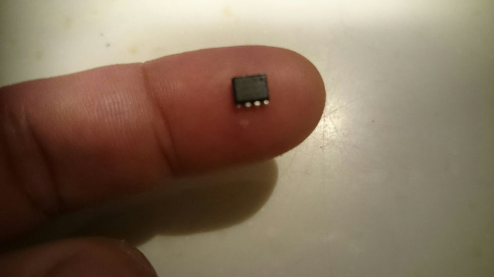
Just to give you a perspective of the size of the chip and it's really NOT a job for the faint hearted and if you are NOT prepare to lose US$18 - US$25 =)
This build took me close to 3 weeks to finish which includes waiting for arrival of parts, wiring / testing with various components and configuration of the software.


The end result of this particular build wasn't satisfactory and I need to go back to the "drawing board" to
Make this build slimmer. One of the option is to remove all the USB, VGA and headphone connectors together with the GPIO pins. Then solder all the parts straight into the Raspberry Pi. Another option is to use the Raspberry Pi Zero but it does also have some constraints and limitations.
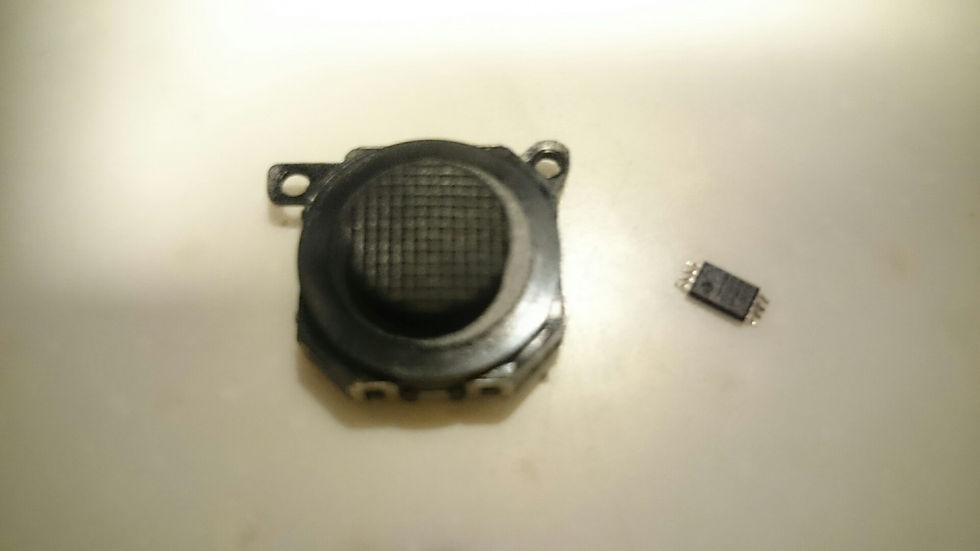
Perhaps to swap out the JoyPad controller to the PSP flat kind Joystick. However, in order to do that, I would need to wire 8 pins of an analog-to-digital converter and the chip is even smaller than the XL1509 (shown above). Refer to the diagram below to get and idea on just how small the analog-to-digital converter is.
All done and said, for now, I'm going to put aside all works in this PiBoy till I get a Raspberry Pi Zero or strip out all the connectors on the B+ (as mentioned above). Will further update you folks hopefully in the near future.
Concurrent to the PiBoy build, I'm also in the midst of building a stand-alone version of the arcade. Check out my next blog for details of that build.


Comments